

Cheap Electronics as a Sudoku Alternative
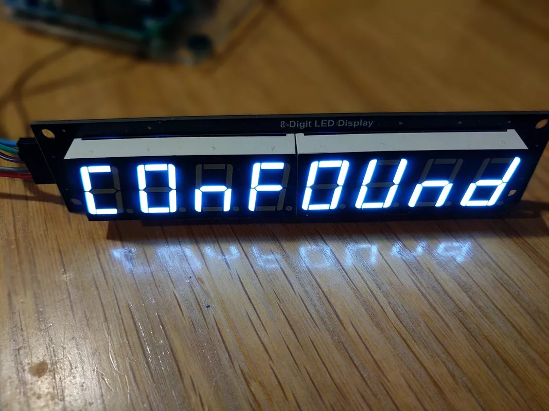
Today's challenge is to drive a cheap 8-digit LED display. I bought a cheap module from Aliexpress. Too cheap! Instead of a nice smart LED driver chip like the MAX7219 as I had expected, it featured instead the jewel of 1980's technology: a pair of 74HC595 shift registers. Let's explore this puzzle!
Bits and Bytes
The two shift registers strongly suggest that we send 16 bits (two bytes) at once. For quick, interactive testing like this, the Arduino shiftOut() function is perfect (see the link for details).
void send_bytes(uint8_t first, uint8_t second) {
    digitalWrite(latch_pin, LOW);
    shiftOut(data_pin, clock_pin, LSBFIRST, first);
    shiftOut(data_pin, clock_pin, LSBFIRST, second);
    digitalWrite(latch_pin, HIGH);
}
Sending all zeros gave no output:
All ones also left the display blank:
Let's try just the first bit in each byte now:

Some success. All of the LED segments, except the decimal point, lit up on just the fourth digit. Let's see if the pattern continues and try the second bit in each byte:

Okay, this time it's the third digit and all the LEDs are lit except for the one in the middle. It seems like the 1s in one of the bytes enable digits, while 0s in the other turns off segments - but which is which?
Let's try all ones in one byte and all zeros in the second:

We've got the bytes! We turn off segments (in all digits) with 0 bits in the first byte, and turn on digits with 1 bits in the second byte. Inverted output (turning on with low inputs) is not unusual, especially
with older parts that could sink a more current than they could source,
but mixing inverted and normal logic together is odd.
Can I Take Your Order?
Now that we have the bytes we just need to poke around (that's a VIC-20 joke for all you old-timers out there) to find the ordering of the bits in each byte. This part was fun until I discovered the annoying order the digits are in:

Enabling the first bit turns on the fourth digit - or the fifth if you'd rather start counting from the right.

The segments within the digit are straightforward. The labeling to the right is standard. On our chip (and transmission ordering) the first bit is mapped to the LED segment marked A, the second to B, and so on, until the last bit which is mapped to the decimal point, DP.
Let's see what we have to do to show the number 7.
We need to light segments A, B, C, and F (old displays used to skip the F). Remembering that we have to send a zero to light up a segment for this device, we need to send 00011010
Running Fast to Stay in the Same Place
Actually, the image above is misleading. We can only light one digit at once. Any more and they'll all look the same - like all the 8s above. To create a useful display we'll have to explore the wonders of multiplexing.
These 8-digit displays contain 64 LEDs, and it's just not practical to drive that many individually. We'd need eight shift registers, or a hell of a lot of GPIO pins. We have to turn the digits on one at a time, but at a rate too fast to see.

What we have to do in this case is enable the first digit, send the pattern for the 1, then enable the second digit then send the bit pattern for 2, and so on - remembering always that it's a zero to get an LED light up. Let's give it a go with the pattern above.
send_bytes(0x20, 0x9f);   // 1: 00100000 10011111
send_bytes(0x40, 0x25);   // 2: 01000000 00100101
send_bytes(0x80, 0x0d);   // 3: 10000000 00001101
send_bytes(0x01, 0x99);   // 4: 00000001 10011001
send_bytes(0x02, 0x49);   // 5: 00000010 01001001
send_bytes(0x04, 0x41);   // 6: 00000100 01000001
send_bytes(0x08, 0x1f);   // 7: 00001000 00011111
send_bytes(0x10, 0x01);   // 8: 00010000 00000001
If we can manage to send this nonsense 800 times a second we'll be able to match the refresh rate of the MAX7219 chip I thought I had ordered in the first place.
An Arduino UNO running flat-out, using the function above and doing nothing at all but refreshing our display managed a refresh rate of 591Hz. Too fast to see certainly. Swapping to the SPI hardware boosted that to 879Hz. Not bad, but not good either. The module that cost $1 more could refresh itself at 800Hz and can control its own brightness.
I think it's time to put this puzzle back in the box.
Downloads
Published 28 Sep 2021