


Automatic Low-Voltage Cutoff
Running a battery completely flat can permanently damage it, lead-acid and lithium-polymer types especially. I put together this circuit to protect a small lead-acid UPS battery. It's cheap, has a high current capacity, and use only very common parts. Did I mention that it's cheap?
Overview
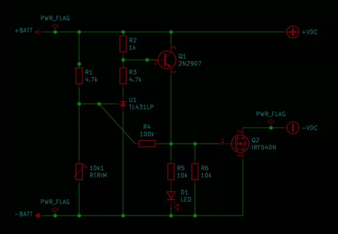
The star of the show is the TL431 'adjustable shunt regulator'. It's a fantastic part, accurate and flexible. Due to its ubiquity in modern power supplies, it is also inexpensive and easy to find. The TL431, fed from an adjustable voltage divider, provides precise voltage detection. A jelly-bean PNP transistor inverts the output signal turning the low-side MOSFET on and off. For good measure we also run a power-good LED.
MOSFET Considerations
The MOSFET needs to be able to switch the full load without getting too hot. Pretty much any power device would do. I used an N-channel device, but doing so meant having to add the PNP transistor and its resistors.
It would have been simpler to skip the transistor and use a P-channel MOSFET directly from the TL431. Actually, I probably should have done just that. While N-channel devices are usually more efficient than the equivalent P-channel type, the truth is that I went with this design because I just happened to have a bag of (probably counterfeit) IRF540N devices handy. When I need to build another one I'll give it a try (and update this article).
Note also that switching on the low-side of the load raises the ground voltage - this doesn't matter in this case, as we are switching a battery, but it is another point against this version of the circuit.
Positive Feedback
The 100k resistor R4 add positive feedback, solving two potentially fatal problems - both of which turned up to say hello during testing.
Firstly, it speeds Q2 through its turn-on phase. While the MOSFET has a extremely low resistance and dissipates very little heat when fully on, it must pass through its high-resistance linear region first. The voltage input from our discharging battery decreases sluggishly indeed. Without enough positive feedback, the MOSFET got very hot as it approached the cut-off point.
Secondly, it adds much-needed hysteresis to the cut-off voltage. The finished circuit cuts off the power at 11.0 volts, and doesn't reset until the input goes back up to 11.8 volts. When you disconnect a loaded battery the battery's voltage rises again. Without hysteresis our power would turn off, then on, then off again as the battery's voltage recovered. Neither our MOSFET nor our load would find that oscillation healthy.
Results
It's working really well. I built mine on some perf-board, inline with the battery's power lead, with a trusty XT-60 connector feeding the load.

At two amps of draw the voltage across the MOSFET is only 160mV, dissipating only a third of a watt. My dinky little heat-sink wasn't needed. Turn off is fast and the hysteresis is enough to keep at least this particular battery off.
Slap-Dash Design
You'll note that most of the resistors have nice round numbers: 1k, 10k, 100k. That's a sure sign of a quick and dirty design. There's plenty of room for improvement there. For example, we're drawing a full milliamp through the voltage divider even when turned-off. I should increase the values of those resistors (and then play around with the value of the feedback resistor too).
Downloads
Published 4 Oct 2021