


AVR Multi-Programmer
I'm about 10 years late to the party, but in this project a cheap Arduino UNO clone becomes a very handy AVR programmer for everything from a little 8-pin ATtiny13 to a 28-pin ATmega.
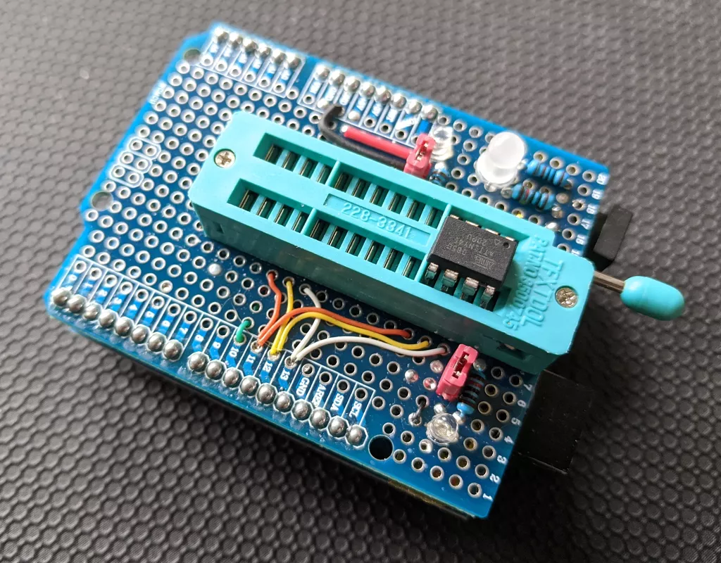
I needed a stand-alone AVR ISP programmer for recent project using the 20-pin ATTiny4313, a device I hadn't used before. I had a couple of Arduino UNOs and some spare shield PCBs, so rather that just breadboard a one-off, I created a nice reusable programmer that can program not only the '4313, but all of the AVR devices in DIP packages that I care about.
The idea came from Adafruit's Stand-alone AVR ISP Kit for the ATmega328. I added the ability to handle devices in the 8-pin ATtiny13 and ATtiny45 series, as well as the 20-pin ATtiny4313 - and anything else with the same pinouts.
Multiple Devices
The In-System Programming (ISP) scheme used by many generations of AVR chips is really elegant: Simply hold the device's reset line low and send bytes over its SPI lines. I'm glossing over dozens of pages of details, but the point is that to program a chip you need only control of the reset and SPI pins. Six pins total, counting the two power pins.
Let's compare the pinouts of the devices I have - restricting ourselves to just the programing pins:

Combined into one

This looks promising to me. There are no obvious conflicts. Would it be okay to just connect everything? IO pins default to their high-impedance input mode during normal operation, would the same hold true during programming? I thought it was worth giving it a go, and so far it's worked well - although I did add jumpers on the prototype to allow for switching off the VCC lines, just in case.
Software and Usage
Simplicity itself. Flash the host Arduino UNO (the one the shield is sitting on) with the ArduinoISP sketch sitting right there in the examples menu. Once that is done, use avrdude to upload code to all sort of fun chips:
# Upload firmware
avrdude -c avrisp -P /dev/cu.wchusbserial620 -b 19200 \
    -p attiny4313 -U flash:w:Candle0005.hex

# Set fuses
avrdude -c avrisp -P /dev/cu.wchusbserial410 -b 19200 \
    -p attiny4313 -U lfuse:w:0xC4:m
Improvements for Next Time™
It would probably have been a good idea to put some protection resistors on the SPI input lines, even just a wee one kiloohm, say. 1206 SMD resistors fit nicely across the pads of the perfboard. There are 3mm green LEDs next to each of the two VCC pins. A 10k dropping resistor, even with the measly 5V input, is not enough. They are really too bright. High efficiency LEDs are quite remarkable. I also experimented with using a red/green bi-colour LED on the MISO/MOSI pins to show activity. Useful to see activity during programming, but the colour effect was underwhelming.
I left room at the bottom of the shield for a button and a OLED screen for stand-alone operation. Unfortunately doing so put the VCC on pin 28 right above the metal shield around the Arduino UNOs USB input, necessitating tape to avoid a a short-circuit. Ooops...
Notes and Links
The prototype has proven useful enough to remain a permanent fixture to the workshop. I'm very pleased with it.
For this article I've experimented with using drawing schematics using the Python library Schemdraw, rather than the EDA package KiCad. Both systems are Open Source of course, but the former produces lovely SVG output, using short Python scripts to declare elements within the schematic.
Updated 31 Oct 2021, first published 18 Oct 2021